Reflowy V3
To build my electronics lab up from first principles, I decided to tackle building a reflow oven first. This is both achievable, and there are a few precedences available which makes this not something that hasn’t been done yet. The venerable Controleo3 from Whizoo has long been an excellent choice if you wanted a hackable DIY reflow oven.
However, I wouldn’t learn anything if I just were to buy a kit. So I decided to tackle it on my own.
Unfortunately, the base reflow oven used by various customers of Controleo3 and some other electronics enthusiasts are not available anymore (or are not available in Europe). Therefore, I chose one of the most powerful ovens (in terms of wattage) with the smallest chamber size that I could find: A Ninja Foodi 8-in-1 Digital Air Fry Oven (SP101).
Unbeknownst to me at the time of purchase, this particular model has quite a few of iFixit guides available which made it a great choice. It also turned out to be plenty powerful and already quite well insulated out of the box. I confirmed that by running the oven on full blast and measuring the temperature with a simple thermocouple circuit and an STM32 development board.
The next step was to install the solid-state relays to control the heating elements and the convection fan.
To install the relays, I removed the main PCB and the control panel. To improve cooling efficiency, the solid-state relays are mounted on a machined piece of aluminium which is installed in place of the old PCB, with the electronics cooling fan taking the heat away.
Once the relays were installed and all wired up, I was able to control the heating elements and the convection fan from any MCU with a transistor (most GPIOs of modern MCUs do not have enough strength to drive the relay input directly, so a transistor, or more commonly, a transistor array is used instead).
Before getting started on the PCB design, I hacked together a prototype board with an Raspberry Pi Pico, a few breakout boards from Adafruit, and one or the other discrete component. I soldered everything together using a perfboard, and 3D printed an enclosure into which I mounted the prototype board and the LCD display.
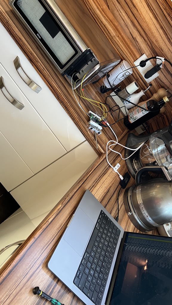 First test setup in my kitchen.
Once I confirmed it working, and made progress on the firmware, which is written in Rust using the absolutely brilliant embassy crates, I started working on the final PCB design.
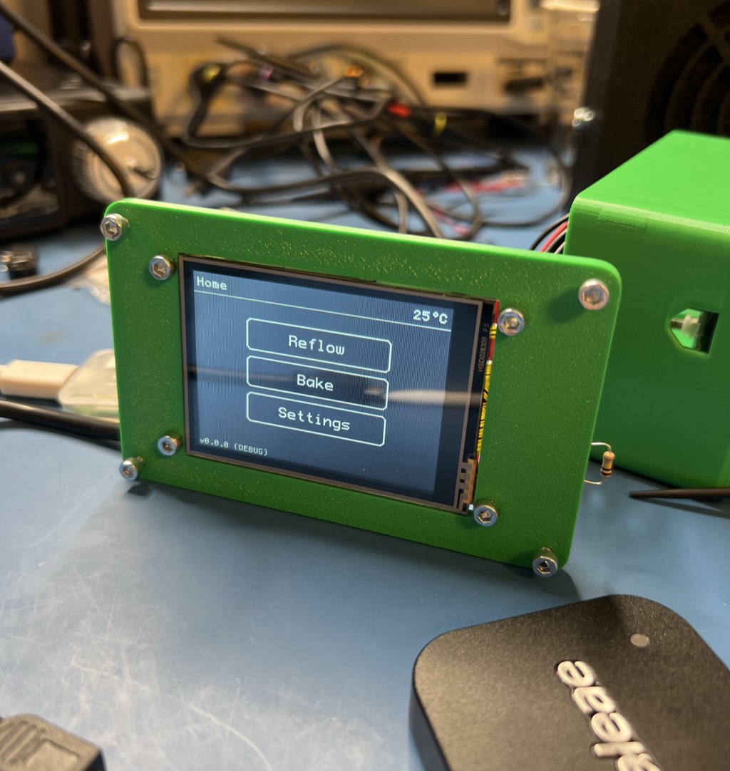 Testing the firmware.
The PCB design was done in Altium Designer. I put an emphasis on cost effective assembly, so the use of passives smaller than 0603 was heavily constrained. Unfortunately, it could not be completely avoided to use some 0402 passives due to the requirements of the RP2040 MCU.
Except for the QFN of the afforementioned RP2040 everything else was easily hand assembled with the help of a reflow oven, a hot plate, or hot air. Fortunately, I had a working prototype board for my reflow oven and could assemble the boards completely in-house.
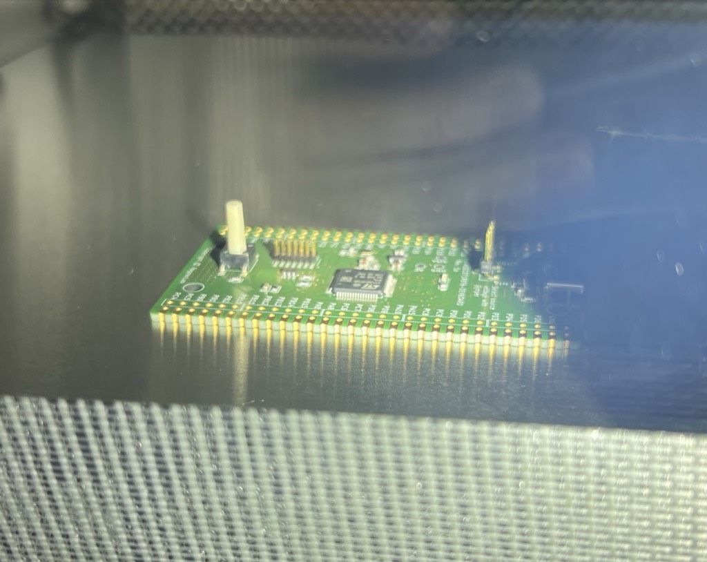 Reflow of the STM32C071 dev board.
Board Statistics
- Layers: 4
- Manufacturer: Aisler
- Components: 90
- Width: 50 mm
- Height: 85 mm
Pictures
Click images to open them in a new tab.
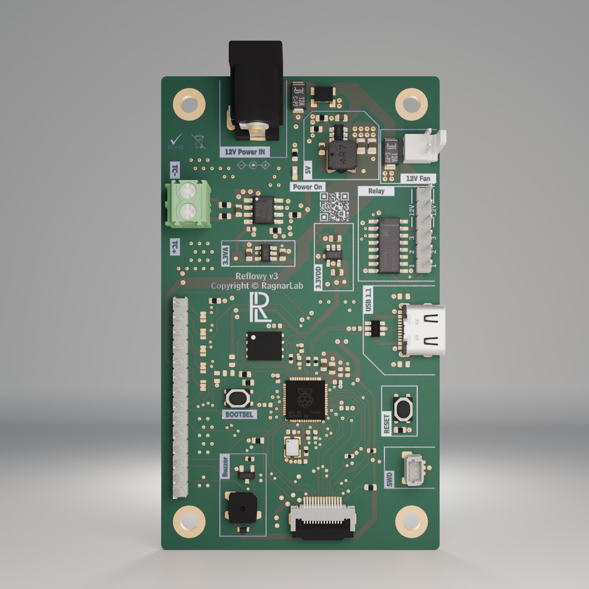 Final PCB
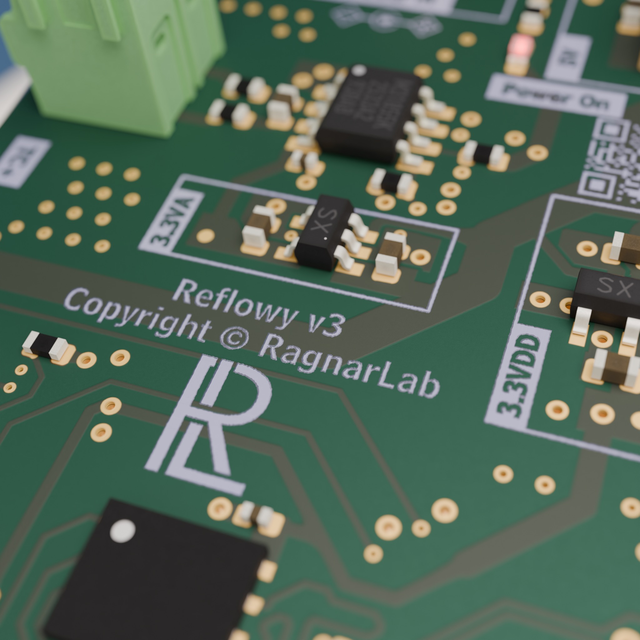 Close up of the final PCB